b4cast - Simulation of Hardening Concrete
The b4cast is advanced software for simulating the temperatures and stresses in three-dimensional concrete structures during hardening. By means of the software, structures are modeled for different construction methods in order to optimize the solution.
It is very important to be careful during the hardening process of concrete. Inappropriate construction methods can cause:
- Freezing before the concrete is strong enough
- Too early evaporation leading to a weak cover layer
- Too high temperature differences leading to crack-formation
- Lack of final strength due to too high temperatures
- Lack of strength at form removal, prestressing or loading
In all cases the concrete structure will be directly damaged and the durability, functionality and appearance will be substantially reduced. On the other hand it is also important not to make more arrangements than necessary. By performing a simulation prior to the start-up of a project, the risk of damage is reduced or eliminated.
The b4cast software is useful for:
- Contractors, in planning construction methods fulfilling requirements and economy limitations.
- Consultants, during the design phase where it is possible to check the planned activities.
- Precast industries, optimizing the production
Before the execution, you can choose a construction method which is satisfying requirements concerning:
- max. temperature
- differences in temperatures
- strength (based on maturity)
- curing (including rate of evaporation or total evaporation)
- freezing
- maximum exploitation of tensile strength (crack-formation)
By means of b4cast you can describe your 3D-dimensional structure and test different construction methods in order to get an optimum solution regarding quality, time and money.
Since b4cast is based on the Finite Element Method and models in 3D, a wide range of problems can be solved.
The computer program is very user-friendly. No in-depth knowledge about the Finite Element Method is required. What is needed is to describe the construction method, start the calculation and check if the results are reasonable.
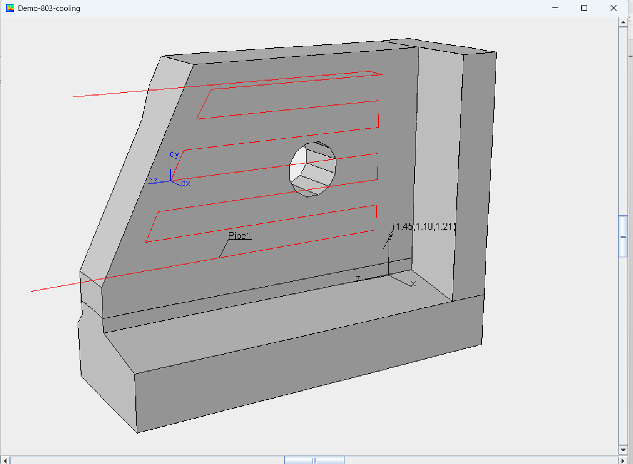
Construction Method
Volumes corresponding to actual castings or other structural parts are defined geometrically. Geometries can be specified directly in the software or STL files can be imported.
The actual execution method includes:
- Choice of time of casting and the casting temperature for each casting section
- Description of the relevant boundary conditions in relation to weather, neighboring structures and substrate. This includes both thermal and structural conditions
- Choice of form types and covers
- If necessary, cooling pipes and heating wires are placed and their performance is described
All parameters can be varied during the entire simulation period.
After performing a simulation, it can be determined whether the desired results meet the given requirements. If not, the model can easily be changed and a new simulation performed.


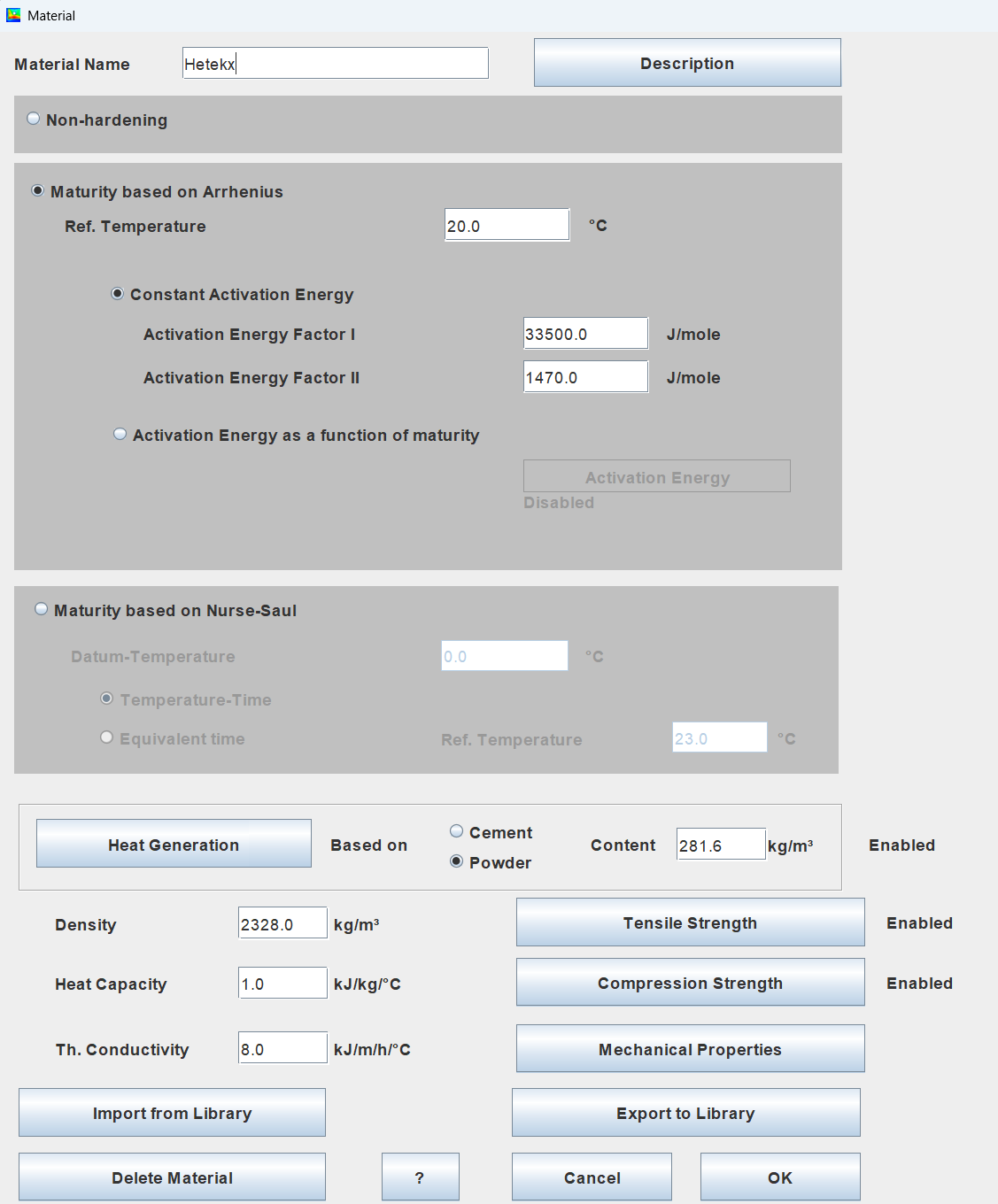
Materials
The hardening concrete is described by:
- Activation Energy/Datum Temperature/Reference temperature
- The Heat of Hydration
- Cement Content
- Heat Capacity
- Density
- Thermal Conductivity
- E-modulus
- Poisson's ratio
- Thermal expansion
- Eigenstrain
- Creeping
- Tensile strength
- Compressive strength
Maturity is based on Arrhenius or Nurse-Saul functions.
Material types with properties that have constant properties can also be used. These are used, for example, for existing structural parts, e.g. previous castings, soil volumes or for supporting/enclosing steel structures.
Materials can be imported from and exported to libraries. In this manner the same material can be reused in different jobs. Together with the software example materials are delivered, which are ready to use.
Thermal Boundaries
The following models can be assigned to surfaces:
- Temperature related to convection
- Wind speed
- Shields: user-defined formwork/insulation etc.
- Flux
- Temperature related to radiation
- Transmission coefficient related to radiation
- Heat from evaporation/condensation
All models are functions of time.
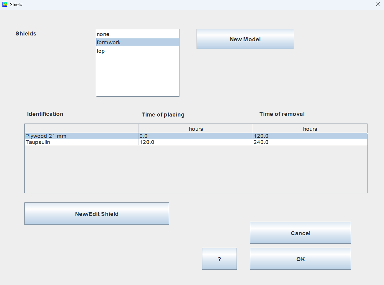
Shields
Through the use of shields (molds, covers and insulation) it is possible to control:
- the size of temperature gradients within a casting in order to reduce local thermal stresses between the center and the edge
- differences in neighboring constructions average temperature which can lead to mutual "global" cracking
- that the properties of the hardening concrete are not destroyed due to freezing or at too high temperatures which can lead to Delayed Ettringite Formation
- the strength development and derived properties thereof such as demoulding time, the need for drying protection, time for tensioning of reinforcement etc..
Other measures can be to use cooled fresh concrete or change the above-mentioned ambient conditions by setting up tents or creating shade.
Artificial internal cooling or heating can be used by embedding cooling or heating pipes or electric heating cables/wires.
Please note that all measures that can be used to meet given requirements may result in other requirements no longer being met. For example, cooling will result in slower strength development.
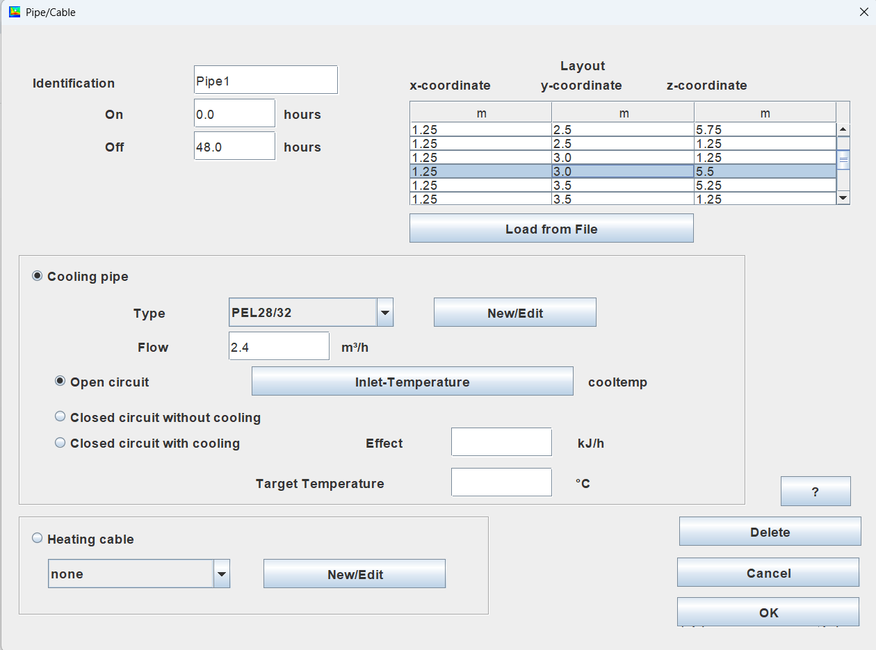
Cooling pipes (Heating pipes)
As part of the simulation results, knowledge of the cooling water temperatures as a function of time and location is obtained.
Cooling pipes can limit temperature differences between the center and edge zones of a structural part and between adjacent structural parts, and also ensure that the properties of the concrete are not destroyed by excessively high temperatures.
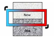
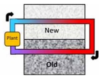
Three types of cooling pipe systems can be defined as illustrated in the following schematic:
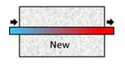
An open circuit requires that there are sufficient water resources in the form of groundwater, water from lakes, rivers or seawater. The inlet temperature is specified corresponding to the source in question.
A closed circuit passing through new and old concrete has the added benefit (besides the cooling itself) of distributing the Heat of Hydration between the two parts, thereby reducing differences in thermal movement and thus reducing the risk of cracking.
If the closed circuit is provided with a cooling plant (the old concrete is not required but an option in this case), the available maximum cooling power and the target temperature can be defined.
In this case the outlet water will be reduced to the target temperature and reused as inlet water.
If the cooling plant does not have sufficient effect, the temperature of the outlet water is reduced corresponding to the present effect. In this case the results show that the desired target temperature cannot be maintained as inlet temperature throughout the entire process. Often it will not be necessary to be able to maintain the target temperature for a period around the time when the concrete reaches its maximum temperature.
If the outlet temperature is lower than the target temperature no energy is removed from or added to the cooling water.
All cooling pipe systems can also be used for heating by proper definition of the target temperature together with a negative cooling effect.
Instead of water, an antifreeze liquid can be modeled if necessary.
Heating cables/wires
Electrical heating cables can typically be used to limit differences in temperature movements between adjacent structural parts and to ensure that the construction joints can be kept frost-free.
Internal heating can be provided by means of embedded heating cables/wires with an effect relevant to the task.
Libraries
Shields, cooling pipes and heating wires can be imported from and exported to libraries. In this manner these can be reused in different jobs. Together with the software are delivered examples, which are ready to use.
Loads/Displacement boundaries
The structure can be modelled with self-weights and external loads.
Displacement boundaries in relation to external restraints can be applied. Displacement boundaries are also used in specifying planes of symmetry.
If none or some displacement boundaries are supplied by the user the software automatically complement boundaries in a way, which makes the structure statically determinate.
The connection between two adjacent volumes can be decoupled. Decoupling is used to model construction joints where one or more displacement components are discontinuous. It can be, for example, a soft joint or related to match casting operations of precast segments. Decoupling is also useful if there is no mechanical interaction with e.g., a ground volume, but still thermal interaction.
Calculation Method
The analyses (thermal- and stress-) are performed by means of the Finite Element Method. The structure is meshed into tetrahedrons. The variation of temperature, maturity and stress within the element is assumed to be parabolic within each element.
Stress Analysis
The mechanical properties of the materials are assumed to be within the linear-elastic strain range.
In practice, this means that the stresses in a structure are not redistributed, for example if the tensile stresses exceed the tensile strength of the material, during the simulation.
In that case, the stresses are no longer accurate but indicate that cracks will occur.
The creep strains are also assumed to be within a range where the creep properties can be considered linear. The development of creep strains results in a redistribution of the stresses in the structure.
Based on the simulation, curing measures can be revised to achieve a crack-free structure through renewed simulation.
In construction joints and other connections the interaction is by default assumed to be perfect so there will be no separation or sliding at the interface between the two construction parts during the simulation.
However, specific connections can be defined as modeled as decoupled in one or more directions.
If it is assessed from an initial analysis that, for example, a cylindrical steel form will detach from a cast column during the curing process (due to thermal contraction and/or autogenous shrinkage), the steel form can be removed at that time and no longer interact with the concrete column.
Results
Results are:
- Temperatures
- Maturities
- Tensile and compression strengths
- Amount of evaporated/condensed water from surfaces
- Stresses, Principal Stresses and exploitation of tensile strength
- Strains, Principal Strains
- Displacements
- 3D Deformations
Results variation in space are presented as contour plots in user-defined sections
Results variation in time are presented as graphs with minimum/maximum-values, average values, or values in user-defined points.
Cross-sections with extreme values can automatically be located.


Licensing
The b4cast software is available with a time-limited license.
The software and license are provided over the Internet.
Free trial| Product | Annual license 1) | Monthly license 1) |
|---|---|---|
| Thermal analysis only | 1500 USD | 200 USD |
| Thermal analysis + Stress analysis | 3000 USD | 400 USD |
| E-mail support during license period 2) | 2250 USD | 400 USD |
|
||
All prices are exclusive VAT, taxes, and duty.
Please state payment method when placing order (bank wire transfer or credit card).
OrderSystem Requirements
The license requires access to the Internet.Operative systems: Windows
Thermal Analysis: min. 4 GB RAM
Stress Analysis without cooling pipes/heating cables: min. 8 GB RAM
Stress Analysis with cooling pipes/heating cables: min 16 GB RAM